Code Club Electronics 5
A few more circuits are below.

Two LEDs wired up normally.

As above with a switch

Note: Switches should align to holes, as per previous images
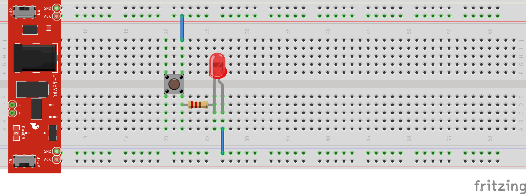
Single LED wired up with two switches.
Tags
| Mastodon | ShellLabs | Join Mastodon |

Code Club Electronics 5
A few more circuits are below.
Two LEDs wired up normally.
As above with a switch
Note: Switches should align to holes, as per previous images
Single LED wired up with two switches.
Tags
| Mastodon | ShellLabs | Join Mastodon |
Code Club Electronics 4 extra
Some of the larger breadboards have power rails that may not be connected, or you may want to put 2 normal size breadboards side by side and clip them together.
In this instance, it is useful to bridge the two sections or boards so the power rails run the full length.

The above illustrates how to do this.
Tags
| Mastodon | ShellLabs | Join Mastodon |
Code Club Electronics 4
Where to get electronics parts from:
I have ordered from a company called Banggood. These links are just a guide, you can more than likely find good offers on the website.
Tags
| Mastodon | ShellLabs | Join Mastodon |
Code Club Electronics 3
Now let's add a switch, so we can turn our LED on and off.
Depending on the type of switch you use, you may have to experiment with which in to connect. It should work as illustrated.
If you have a reed switch, you can try one too, and use a magnet to activate the switch.

An LED is like a bulb, but one way, the short lead goes towards the ground. As long as the resistor is in series, it can be before or after the LED.
Tags
| Mastodon | ShellLabs | Join Mastodon |
Code Club Electronics 2
So now we have a powered breadboard, disconnect the power (important) and connect up a LED (Light Emitting Diode) and a resistor in SERIES.

An LED is like a bulb, but one way, the short lead goes towards the ground. As long as the resistor is in series, it can be before or after the LED.
NOTE ABOUT COMPONENTS
Tags
| Mastodon | ShellLabs | Join Mastodon |
Code Club Electronics 1
As we are undertaking varied projects at Code Club, I am going to put together a guide on creating some simple circuits.
I have a few breadboard power supplies that connect to a breadboard as illustrated below.

The following video, illustrates how to create the diagram in Fritzing but if you follow the layout you can produce the same circuit with a breadboard and components.
I have embedded a video below.
The idea here is, that followers can both use software and real components to build up software, being able to plan where components are to go, can be really useful.
Note the orientation of the PSU so that the +v and gnd pins are also matching the rows for +v and gnd (red / blue)
Also note that the PSU as +v in and can produce either 3v or 5v, any circuits MUST be given the correct voltage as this will determine values of resistors used.
Tags
| Mastodon | ShellLabs | Join Mastodon |